Sunday, 1 May 2016

Sprint EFI work

Not complete yet but good progress made.

I collected the inlet manifold on Friday, which has had a boss welded on for the Coolant Sensor


Next job was to strip out the old carbs and ancilliary items - as its a slant4 there's lots of room when everything has gone.


I have also removed the battery as I want to relocate this to the boot, so I can fit a larger battery and have room for the airbox.

So time to fit the new manifold and refit heater hoses, with a new stainless steel heater pipe - the old one was somewhat rusty


next fit the injector bodies, so I can make up the wiring loom - I have run separate looms for sensors, and the injectors to reduce interference to the sensor circuits

map sensor with loom


injectors wired, with plug for IAT sensor visible

 
coolant sensor and wiring just visible bellow the thermostat housing
 
 
I have now sorted out the inner wing wiring, the loose fuses have gone to be replaced with a fuse box, and a new earth strap was made and fitted, and also on the body terminal you can see the negative battery wire, which will go to the boot with the positive cable, which is now fitted to an insulated stud, which has the headlamp and fan relays connected to it with the starter motor feed - I now have to run the 2 battery wires to the boot, but I shall do that when I fit the fuel lines


Trial fit of the airbox, air horns and the IAT sensor - this needs the boss "glassing" into place, when I fit the air intake to the airbox, I am intending to fit a large cone filter behind the grill where the battery normally fits and feed this to the middle of the airbox, coming up into the airbox from underneath, between cylinders 2 and 3 - this will also let me fit a MAF in the airfeed, if I want 
 
 
 The throttle is also connected and the fuel pressure regulator


I trial fitted the new batter cables to a loose battery, just to see if everything works as it should - all the wing wiring mods were correct, and Megasquirt now shows coolant and air temp correctly, and I could calibrate the throttle position sensor. I am not sure about the MAF sensor though - it needs the wiring or perhaps the pin outs on the connector checking as there seems to be no change in the readings when you "suck" on the input.

Apart from that I need to fit the battery cables, fuel lines, swirl pot and the lambda sensor - so nearly there

Saturday, 23 April 2016

The Sprint works on EDIS

Todays job was to get the Sprint working on EDIS,

So I started by making plug leads


and finishing the EDIS loom


I also fitted the wideband sensor Air Fuel Ratio Meter


So Edis loom and plug leads fitted


Next was to mount the trigger wheel and sensor, easier than it sounds as I needed to remove the radiator to get some working room, but all done, and radiator replaced


Disconnect the old coil ignition, power up the EDIS and see what happens, when I turned the key .. it started immediately.


One tiny tiny issue, when checked with the strobe, it was firing at 9 deg BTDC, instead of 10 - not bad though, and Microsquirt has an "ignition offset" setting to correct this, so well pleased.

However I do need to replace the connector on the sensor, its poorly fitting, although it was supplied with the sensor

Next job is the fuel system and relocating the battery to the boot.


Sunday, 17 April 2016

Grrr HCR 1 Dolly Sprint 0 and EFI thanks to Nick Jones

I know this has been posted on the CT forum, but thanks to Nick Jones it does go on to other things
 
At least this year we got past the halfway mark.

Nearly in Norfolk after the first 2 Counties of the second half, miss-fire, then no power, then stopped engine.

It had fuel in the carb float chambers, so check the points gap, bumped the car to try and turn the rotor, wouldn't move, assumed it wasn't in gear, tried again, no joy !

I found I could turn the rotor arm by hand.

Telephoned for recovery - we'll be two hours before we can get to you - fair enough at 3am Sunday morning

Pulled the distributor, drive gear and thrust washer left in block - the roll pin  between the drive and the shaft had sheared off.

Bear in mind I have just spent a fair few pounds on getting the distributor reconditioned I was not happy, plus there's now 2 small pieces of roll pin floating around in the sump.

I cut up our clip board clip to fashion a drift, and removed the rest of the roll pin from the shaft - I still had the failed distributor from the RBRR in the boot, so I drifted the roll pin out of this, to find it was also broken, however the broken bits from the two distributors were about the length of a new pin, so I inserted these in the new distributor and drive, (they were a little loose) and secured them with some mig welding wire through the middle.

Put the distributor back, re-timed it and it fired up and ran OK.

About 4am and the recovery truck turned up.

Decided at this point to take the recovery option, as I wasn't sure why the roll pin had failed, and my repair was a bit of a bodge.

Bad pin, poorly fitted ??

I think its getting replaced with a drilled and tapped hole and a high tensile cap bolt secured with lock tight
 
This was my bodge fix on the night showing the welding wire holding the 2 halves of the roll pin in place
 
 
Needless to say I have now fitted a new roll pin (and kept one for spare).
 
Nick said that it was a bizarre fault and I should EFI it to get rid of the distributor - now I have most of the bits to convert the Sprint, but simply hadn't got round to it, so without wasting more time I started getting the parts out of storage, and started seeing what needed to be done.
 
I did a trial fit of the Jenvey bodies on the webber manifold (fuel rail and injectors fitted too)
 
 
This revealed the first issue, the Jenvey bodies only need an O ring to seal against the manifold,
 
and don't need the anti vibration mounts that the manifold came with
 
however without the vibration mounts the studs supplied are too long, so I need some short UNC studs. I also need to get a boss welded onto the thermostat housing on the manifold for the Megasquirt temperature sensor - I have now ordered an ally boss, and the studs have been replaced with UNC bolts for now. Still the throttle bodies do look good !
 
 
Next issue was to find a home for the Microsquirt controller and relays, behind the glove box looked ideal for me, especially as there were 2 holes ready made for mounting, and just the right size for rivnuts
 
 
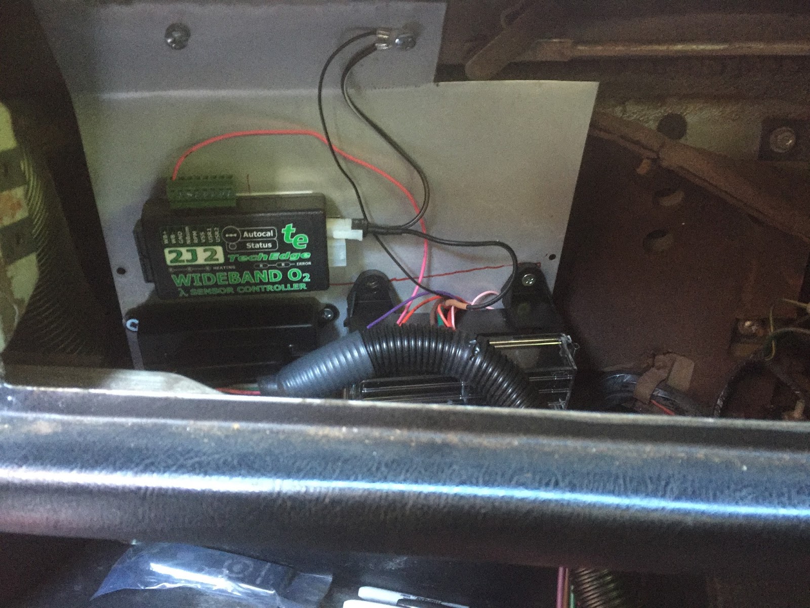
  And here's the ally plate made up and fitted
 
 
 next job was to mount the various components to the plate
 
 
There's the Microsquirt, a combined relay and fuse box, and the innovate wideband sensor controller
 
and wired up tested and working - I needed to calibrate the sensor, which needs doing in free airspace, not later when mounted in an exhaust
 
 
and now fitted to the car
 
 
The glove box still fits, and I can still get to the fuses, relays and programming port from the parcel shelf.
 
I got this wired up to battery, engine ground and ignition sense, and all worked OK.
 
Next item was the coil pack and edis module which are now mounted
 
 
and wired with the exception of the crank sensor, I am moving that from the position I had originally intended for it, so the timing marks will be more visible - I also must get some loom tape for the wires. Next weekend I hope to get the car running on edis (as by default that will run the engine at 10 deg BTDC - limp mode), need to make up plug leads too.

Saturday, 2 April 2016

HCR Preparation

Better late than never !

I have been too busy to work on cars recently, but it was time to attend to a number of jobs on the Sprint so that its fit for the HCR.

First off I replaced all the flexible petrol pipes fitted by the PO, they were not ethanol proof and were all leaking petrol.

Then it was time to attend to the distributor. The previous one had been bodged together from 2 units at the finish of the RBRR, so I could make it home, having limped the car from Didcot to the Plough.

I sent a spare sprint distributor off to H&H ignition solutions in Dudley, and got back a new looking one fitted with electronic ignition, fitted it looked like this


Its certainly sorted out the "points scatter", and the strobe timing light now gives a nice steady flash against the timing marks, without sudden jumps,

Next job was to replace the front tie bars - this is why - look at the wear where they go through the subframe


I got these adjustable replacements from Sprintspeed, this lets you adjust the length, the ST ones were 5mm shorter which is supposed to improve the handling


The final task was to replace the battery, during the RBRR I had intermittent issues with the electronic Davis Craig water pump controller when driving at night, AJP put this down to a faulty battery, and it seems that he was right as the problem has now gone away with this fitted


Finally a parcel of parts arrived this week, its a complete set of NOS gearbox internals for a Sprint gearbox, excepting the input shaft and the two RHP bearings, and the syncro cones - although I have already got 2 new sets of Stanpart ones, and Chris Wittor is supplying the bearings.


I shall be rebuilding my spare gearbox soon,,,,,,,,,,

See you all at the HCR

Tuesday, 17 November 2015

A big package

A heavy parcel arrived at work for me today, 60 ish kg apparently.

In a wooden crate, and wrapped in grease paper
 

So after unwrapping this is what I found, a NOS standard Sprint block - late model too, with the enlarged water pump to jacket waterway and no jackshaft wear present or damaged threads


and as my new pistons don't fit !


its off to Chesman Engineering later this week for a bore and hone

That's part 1 of the new engine underway

Sunday, 3 May 2015

Sprint and TR5 Work

I had been meaning to lift the rear suspension  on the Sprint, via the adjustable spring seat platforms on the dampers since the RBRR.

While on that little jaunt, the ocassional bottoming out of the rear suspension had been put down to 2 fat bastards - Andy and Myself and a boot full of spares, but on the HCR I had the same issue with Anne as a co-driver - and I daren't say that she is overweight.

Looking at the car, even with no passengers the car sat lower than it should, so the tail down attitude must have been due to the rear springs settling, so this weekend I got the C spanner out and adjusted the platforms. With the seats at their highest setting, I gained another 1" of height - if I still have a problem I think new springs of a better quality will be required, but it now looks like this will be fine when driven.


I have also taken the time to fit some sound deadening material under the bonnet - it makes the engine much quieter, and the bonnet now shuts with a "thud" instead of a "clang" - This stuff is made by dynamat, and is foil ontop of a 10mm layer of foam


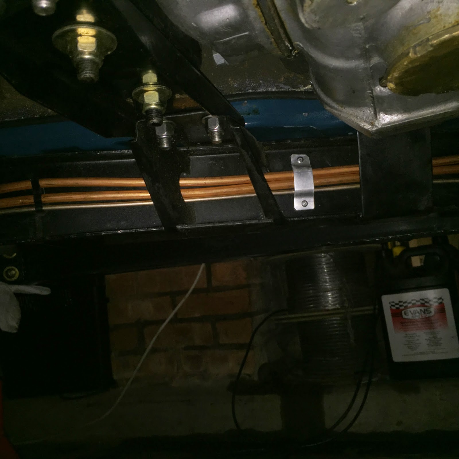
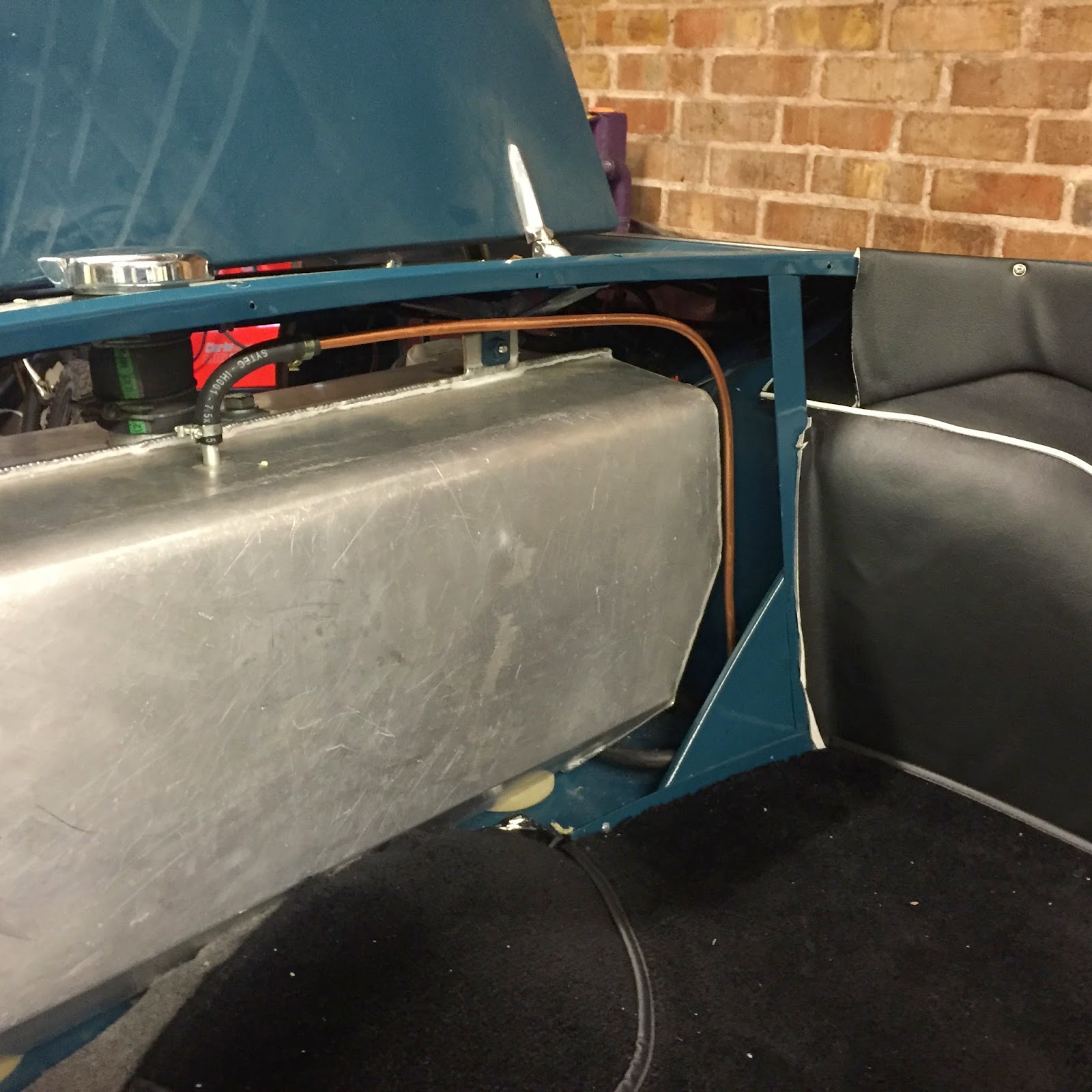
Back to the 5 and I finally got the fuel pipes finished and clipped into place.


I nearly forgot the tank vent


Wiring next !

Saturday, 25 April 2015

TR5 EFI

Today was the day to get on with the EFI system

I needed to fit a lift pump to feed the swirl pot, which I fitted in the rear inner wing. This is made by webcon, and has an integral high pressure pump


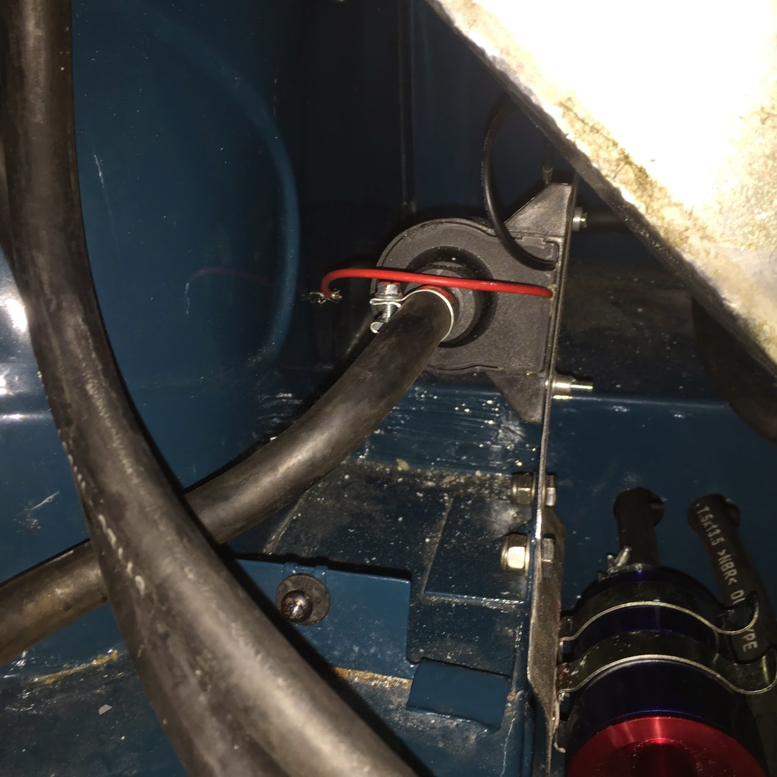
The lift pump, which will "suck" was fitted to a bracket that I made and fits in snugly under the fueltank. this mounts to two existing bolt holes on a bracket, the swirl pot was fitted via rivnuts. The lift pump has a coarse filter on its input.


The same bracket holds the high pressure filter, fitted after the efi pump


 The lift pump feeds the bottom of the swirl pot, and the restricted return goes back into the top of the fuel tank


Feed to the lift pump

I then fitted the high pressure fuel regulator, with a copper pipe return to the back of the engine


I had contemplated bring the fuel lines up on the manifold side of the car - normally they run to the other, distributor side as thats where the mechanical fuel injection sits, but in the end I decided to keep to the normal fuel pipe routing, and ran two rubber hoses from the manifold fuel send and return, round the back of the engine, to the normal fuel pipe positions.


I have just about finished fitting the send and return pipes down the chassis, but I need 2 grommets to pass the fuel pipe through the floor under the fuel tank, and without these I couldn't complete the work. Once these are fitted I'll finish clipping the fuel pipe to the chassis rails, and complete the job.

Before anyone asks I have flared the ends of the copper pipe so that a good reliable seal is made to the rubber.

I need to wire up the pumps, but thats a job for when I finish the wiring

Where am I?